Deadwood and Keel
With the inside filleted and glassed, work moved back to the outside. We
flipped the dinghy back upside-down. Not pictured is the removal of the
wire ties. This was a quick two-person job: one person working with wire
cutters and vise grips to pull the wire through, the other person with a
soldering iron to heat the wire. With this process, we had no issues with
any of the wires sticking in the hull.
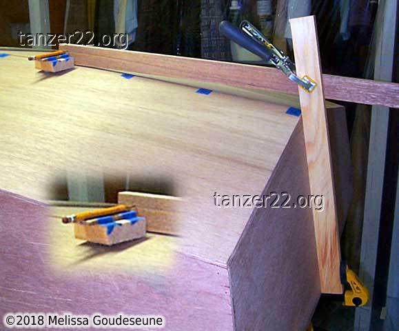
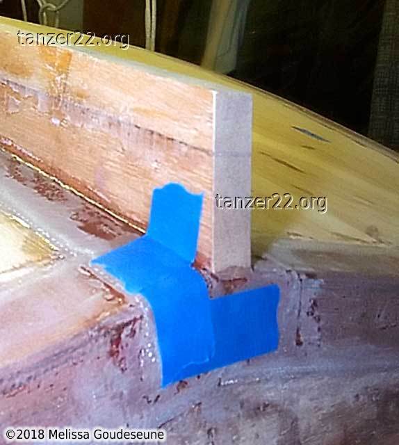
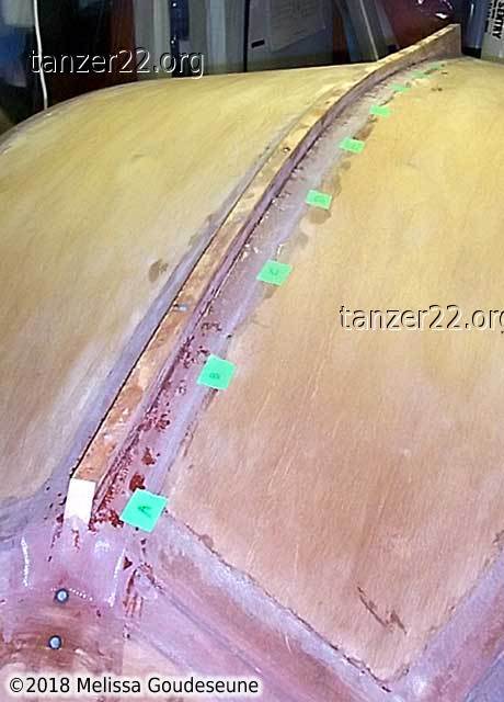
Creative use of clamps allowed me to easily mark the curve of the hull on
the deadwood. The inset shows a closeup of the wood block used to mark the
curve.
With the deadwood cut, it is fitted in the proper location under the keel.
At this point, work moved on to the keel itself. I wanted the keel to be
as close a fit to the hull as possible, for strength and lightness (less
epoxy filler needed).
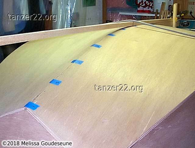
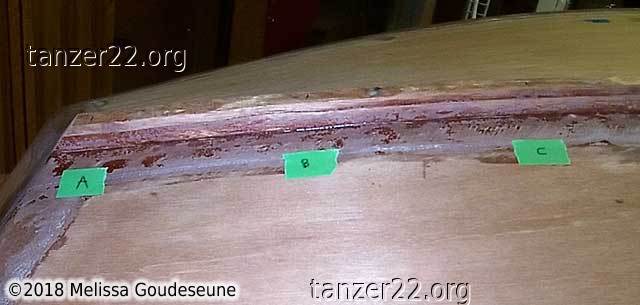
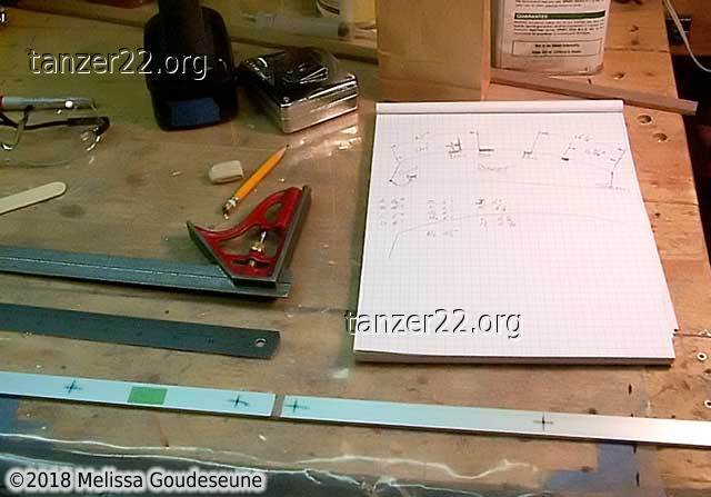
First, I marked off stations at regular spacing on the hull and keel.
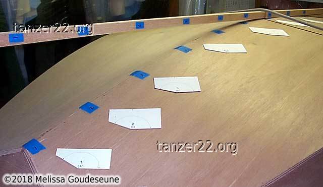
Next, I measured the angle of the hull at that location, and made up a
set of angle templates on the computer.
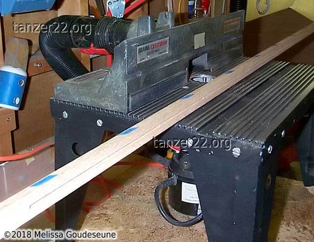
From the angles, I calculated how deep to cut a V into the keel using my
router table. With the deepest part of the V routed out, it was
now simple to use a scraper and a file to make the sides of the V.
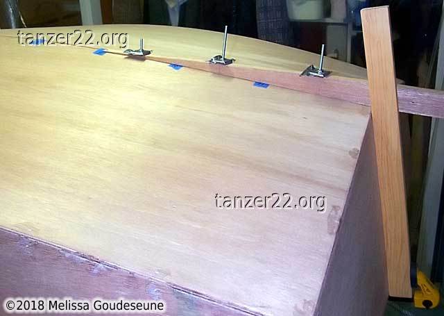
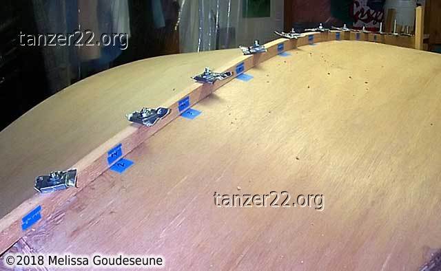
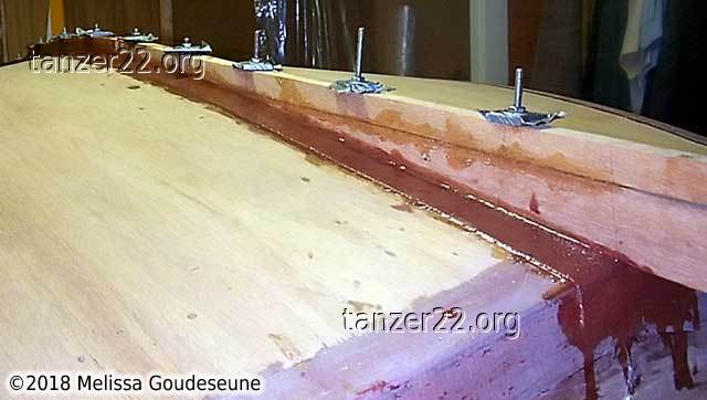
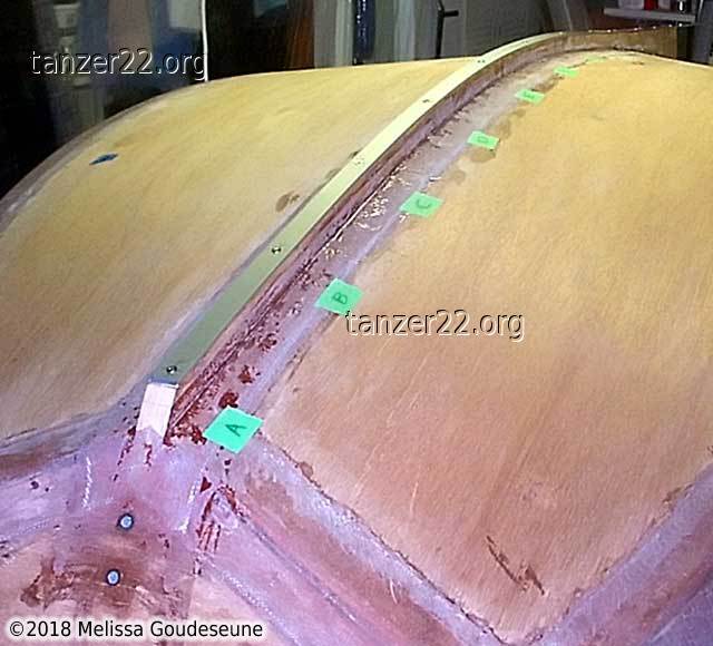
Moving back to the deadwood, you can see the screws I used to clamp the
deadwood. This was test-fitting prior to epoxying the keel.
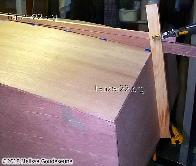
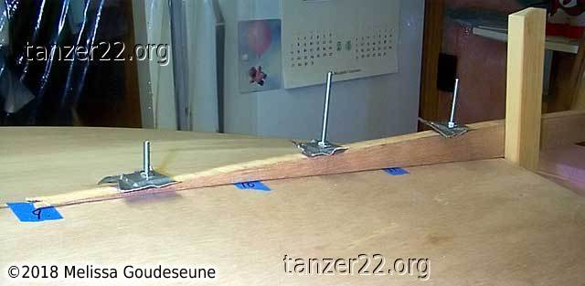
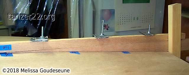
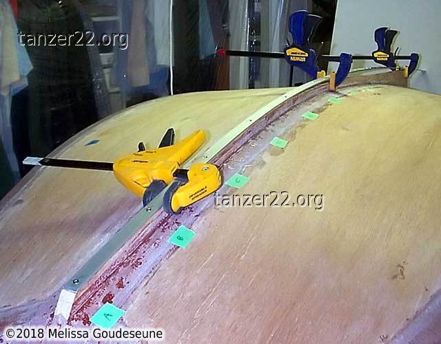
These two photos show the keel being clamped as well. In photo 2, note that
the keel has been partially ripped horizontally on the bandsaw. This
allowed the forward section to more easily conform to the curve of the hull.
The amount of shifting between the two "plies" is shown by the blue tape on
the side of the keel.
Epoxying the keel
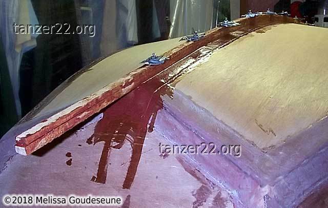
First, I applied a layer of 9 oz fiberglass over the center join of the
hull bottom. Holes were poked in the fiberglass to allow the clamping
bolts to go through. Then, the keel was installed with thickened epoxy,
and the bolts were tightened down.
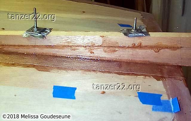
The gray washers are 1/4" plywood covered in duct tape. Once the epoxy cured,
they were fairly easy to remove from the screws. The screws themselves were
stuck by the epoxy. To remove the screws, I heated them with a butane torch
and then turned them out with a screwdriver (don't use your fingers!).
Also note the waxed paper visible in the photo 2. I taped it in place
to catch the inevitable drips from the keel epoxy, making cleanup easier.
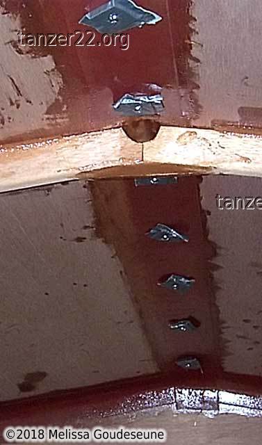
This is the view from inside the hull, showing the same washers as used
on the outside.
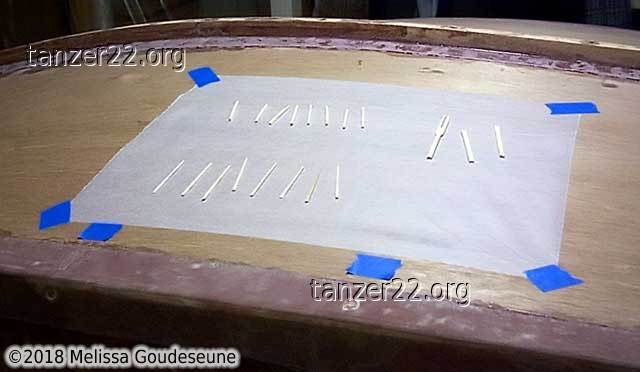
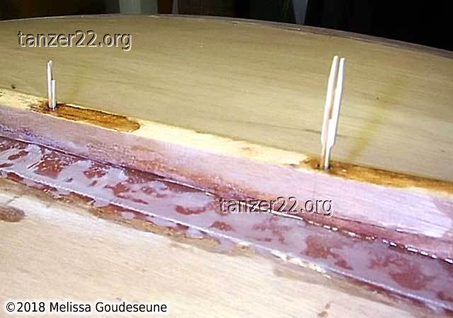
Once the screws were removed, the screw holes were filled with wood
and epoxy. I used toothpicks and cocktail forks, and trimmed them flush
after the epoxy was dry.
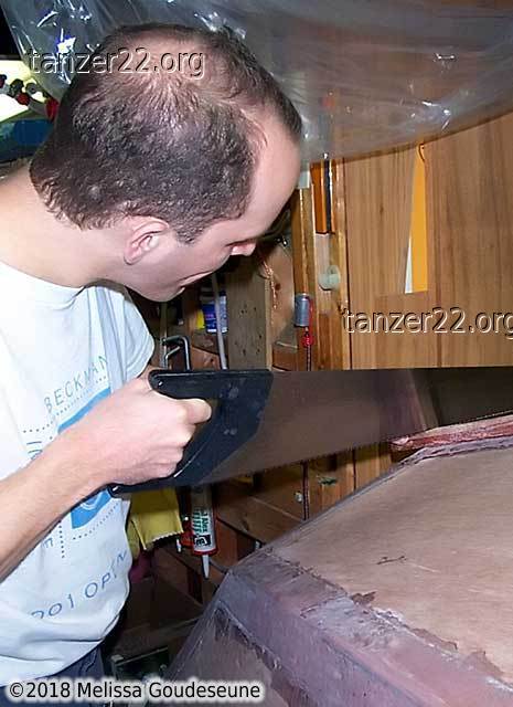
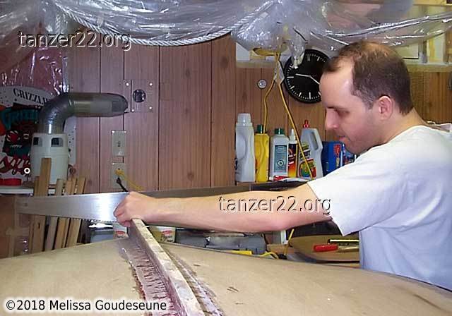
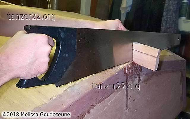
The next step was to trim the excess overhangs of the keel at the bow and
stern. These were rough-cut using a hand saw, and trimmed exactly using a
Fein Multimaster at a later time.
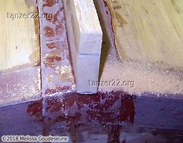
One spot on the keel required a bit of filler before doing the final
epoxy-coating of the dinghy prior to painting.
Keel Runner
For the keel runner, I bought two sections of 1/8" x 3/4" x 4' aluminum at
Home Depot. In retrospect, I should have gone to a metals retailer and
purchased a single piece of the correct length.
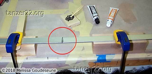
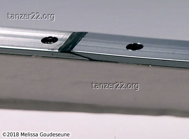
It would have been a waste to not use them, so I needed to find a way to
join them. I used JB Weld to glue them together. My first attempt using a
butt joint only survived about 10 seconds of handling. The second time
using a scarf joint held up much better.
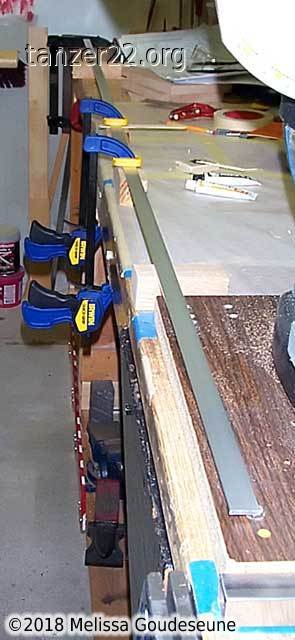
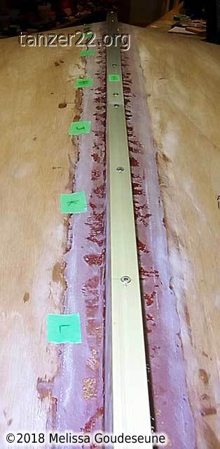
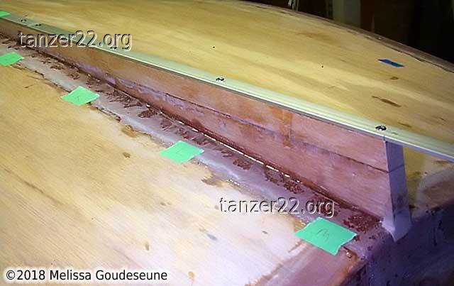
As with installing the keel, I marked off stations for the screws to attach
the runner to the keel.
These holes were marked and drilled on the aluminum runner.
The holes were then drilled in situ, with the screws installed sequentially.
The three clamps helped keep the runner in place and centered on the keel.
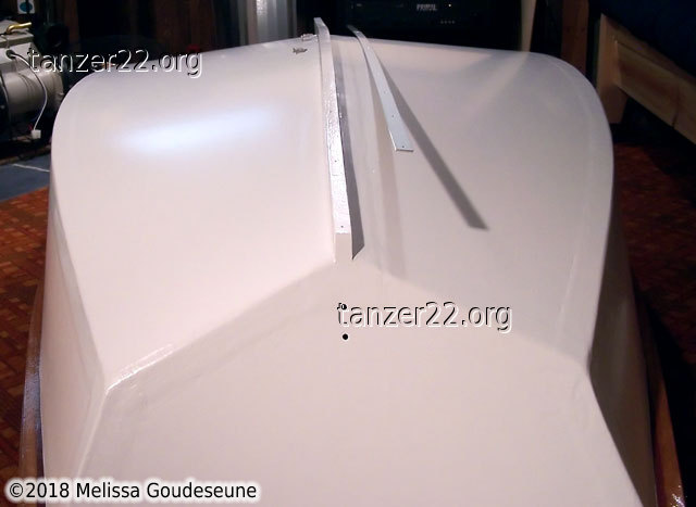
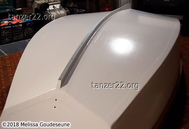
Once the dinghy was painted, the keel runner was permanently installed.
These two photos show the runner and the screws ready for installation.
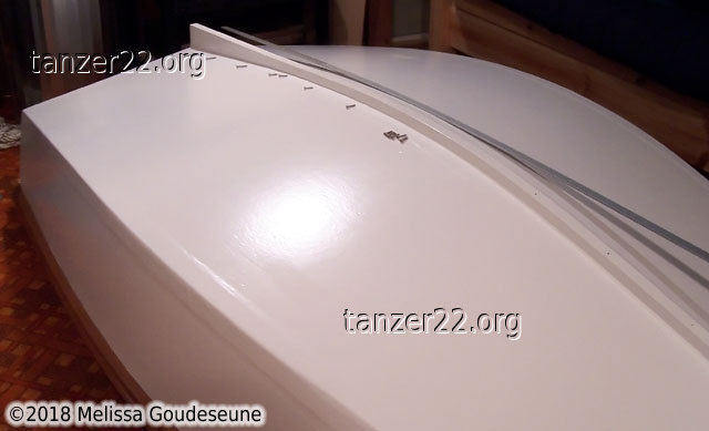
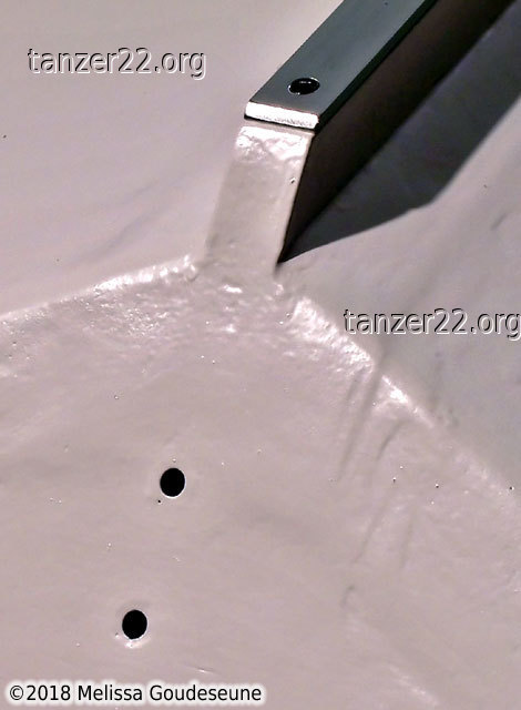
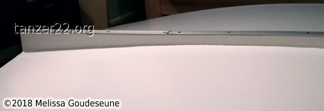
Here is the keel runner installed, as well as closeups of the bow,
deadwood, and the aluminum scarf joint.
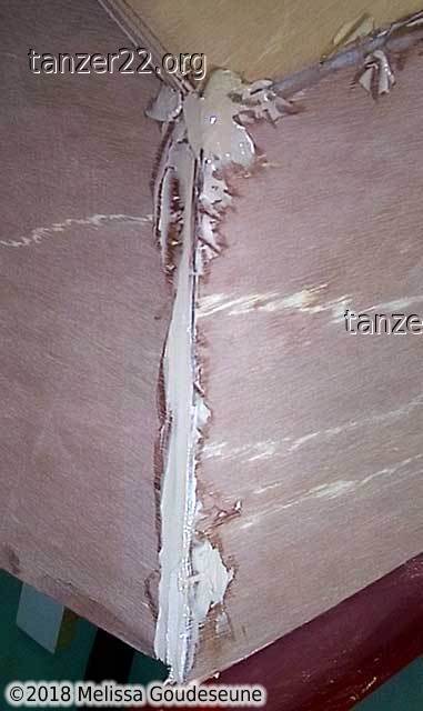
Outside Chines
Before glassing the outside chines, it was first necessary to fill any
remaining voids at the plywood edges. I used epoxy with WEST 410
microlight fairing filler.
As with the inside seams, I used 9oz 3" fiberglass tape. I pre-cut all the
fiberglass pieces and tacked them to the hull with spots of cyanoacrylate
glue (CA glue; a common brand name is "Krazy Glue").
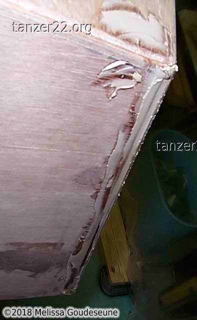
In photo 2 you can see the double layer of cloth at the widest part of the
hull. I did this in anticipation of the fiberglass wearing through from
launching. I also could have put a rub strip of metal or wood outside the
hull. However, given that I don't normally plan to launch from a beach, I
opted for the lighter and simpler solution.
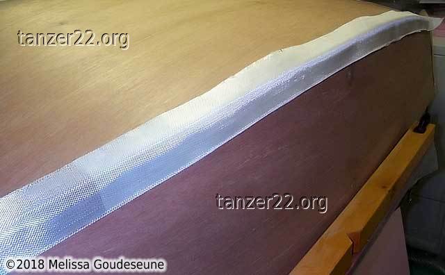
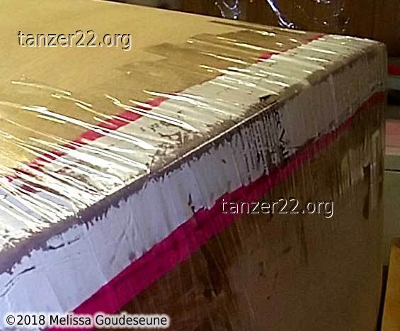
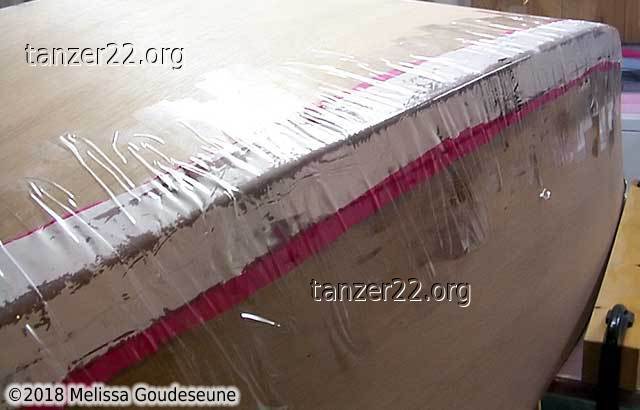
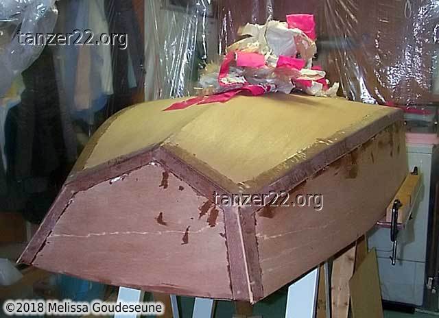
One of the drawbacks of heavy fiberglass cloth is that it doesn't really
want to sit on an outside corner -- it would rather be flat. To solve
this, I adapted the technique of vacuum bagging to clamp the fiberglass
while the epoxy cured.
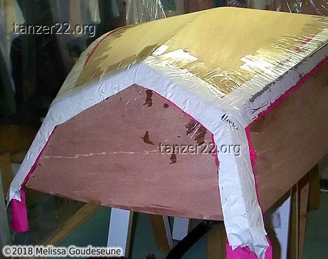
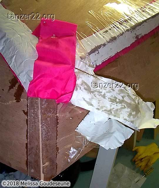
Once the fiberglass was wet out, I covered it with a layer of pink nylon
cloth.
The epoxy doesn't stick to the nylon, and is able to pass through the
nylon. Newsprint above the nylon absorbed any excess epoxy. Then, clear
packing tape was used to apply pressure to the fiberglass.
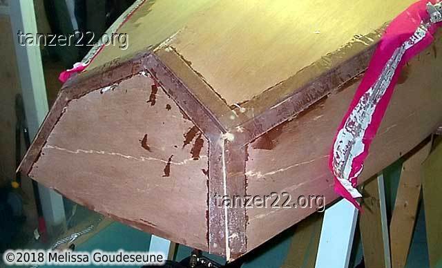
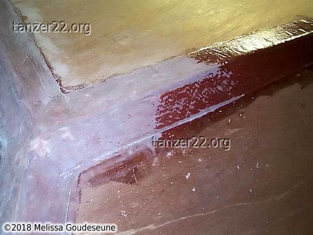
Here you can see how nicely the fiberglass came out.
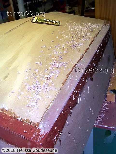
A fill coat of epoxy and microballoons was applied over the fiberglass, and
then scraped down as far as possible to a smooth layer that would just hide
the weave.
© 2018 Melissa Goudeseune